Overview
A RISC-V pipelined processor is a CPU designed using the RISC-V instruction set architecture (ISA), optimized for performance through instruction pipelining. Pipelining enhances instruction throughput by allowing multiple instructions to be executed simultaneously at different stages.
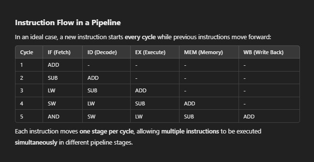
This structure enables one instruction per clock cycle execution, improving CPU performance compared to single-cycle execution.
Pipelining in RISC-V Processor
A pipelined processor breaks down instruction execution into multiple stages, allowing new instructions to start before previous ones finish.
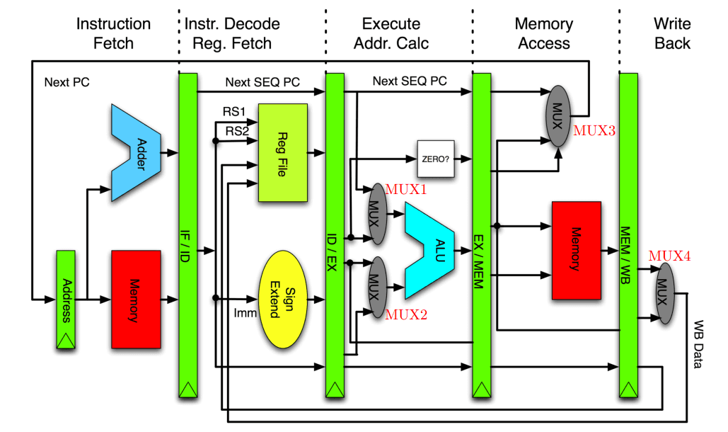
Basic 5-Stage Pipeline
Instruction Fetch (IF): Fetch instruction from memory.
Instruction Decode (ID): Decode instruction and read registers.
Execute (EX): Perform arithmetic/logic operations or compute memory addresses.
Memory Access (MEM): Read/write data from memory (for load/store instructions).
Write Back (WB): Write results back to registers.
Instruction Execution in a RISC-V Pipelined Processor
In a RISC-V pipelined processor, instruction execution is divided into five pipeline stages, ensuring multiple instructions are processed in parallel. Each instruction moves through these stages step by step, allowing efficient utilization of CPU resources.
Five Stages of Instruction Execution
Each instruction follows these five stages in the pipeline:
1. Instruction Fetch (IF)
The instruction is fetched from instruction memory (ROM or cache).
The Program Counter (PC) holds the address of the instruction to be fetched.
After fetching, the PC is updated to point to the next instruction.
🔹 Key Components: PC, Instruction Memory
Example :
2. Instruction Decode (ID)
The instruction is decoded to determine its type (R-type, I-type, etc.).
The required register values are read from the register file.
Control signals are generated to execute the instruction.
🔹 Key Components: Control Unit, Register File
Example:
The opcode is identified as an R-type instruction.
Registers x1 and x2 are read for execution.
3. Execute (EX)
The ALU (Arithmetic Logic Unit) performs the operation.
If it's an arithmetic instruction (
ADD, SUB, MUL) the ALU computes the result.If it’s a branch instruction, the ALU evaluates the condition.
🔹 Key Components: ALU, Immediate Generator, Branch Unit
Example:
ALU computes
x3 = x1 + x2
4. Memory Access (MEM)
For load/store instructions, memory is accessed.
LOAD (
LW x3, 0(x1)) Reads data from memory tox3STORE (
SW x3, 0(x1)) Writesx3into memory.
For other instructions (like ADD, SUB), this stage is skipped.
🔹 Key Components: Data Memory
Example
Reads memory at address stored in
x1and loads it intox3.
5. Write Back (WB)
The final result is written back to the register file.
This happens only for instructions that modify registers (ADD, LW, MUL, etc.).
🔹 Key Components: Register File
Example
The result
x1 + x2is stored back into the register.x3
Data and Control Hazards
1. Data Hazards
A data hazard occurs when an instruction depends on the result of a previous instruction that has not yet completed its execution.
Types of Data Hazards
(i) Read After Write (RAW): True Dependency
It occurs when an instruction needs a value that a previous instruction is still computing.
Example:
Forwarding (Data Forwarding/Bypassing): Send result directly from EX/MEM pipeline register instead of waiting for WB.
Stalling: If forwarding is not possible, insert a stall (NOP instruction).
(ii) Write After Read (WAR) - Anti-Dependency
It occurs when a later instruction writes to a register before a previous instruction reads from it.
Example :
Solution:
Usually not an issue in simple pipelines because instructions are written at the WB stage and read at the ID stage.
Register renaming can prevent conflicts in more advanced architectures.
(iii) Write After Write (WAW) - Output Dependency
Occurs when two instructions write to the same register, but the second instruction writes before the first one completes.
Example:
Solution:
Not an issue in simple pipelines because writes happen in WB stage in order.
In out-of-order execution, register renaming is required.
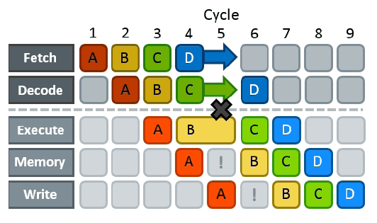
2. Control Hazards
A control hazard occurs when the processor does not know the outcome of a branch instruction and incorrectly fetches the next instruction.
Example of a Control Hazard:
Techniques to Handle Control Hazards
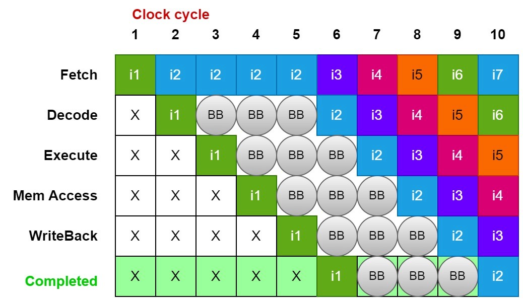
(i) Stall (Pipeline Freezing): Simple but Inefficient
The processor waits until the branch outcome is determined.
Causes a pipeline stall, reducing performance.
(ii) Branch Prediction: Fast but Risky
The processor guesses whether the branch is taken or not.
If the guess is correct, the pipeline continues smoothly.
If the guess is wrong, incorrect instructions are flushed, and the correct path is executed.
Types of Branch Prediction:
Static Prediction: Always predict taken/not taken (simpler but less efficient).
Dynamic Prediction: Uses Branch History Table (BHT) or Branch Target Buffer (BTB) to predict based on past behavior.
(iii) Delayed Branching: Requires Software Support
The compiler reorders instructions to fill branch delay slots with useful work.
RISC architectures (like MIPS and RISC-V) often use this technique.
Features of a Pipelined RISC-V Processor
Forwarding Unit: Reduces stalls by forwarding data from later pipeline stages.
Stall Control Unit: Ensures proper pipeline operation during hazards.
Flush Mechanism: Clears incorrect branch predictions.
Repository of the Project : Click Here
Conclusion
In a RISC-V pipelined processor, hazards pose a major challenge in ensuring smooth instruction execution. Data hazards occur due to dependencies between instructions, while control hazards arise from branch instructions. These hazards can significantly impact pipeline efficiency if not properly managed.
To handle these issues:
✅ Data hazards are mitigated using forwarding, stalls, and register renaming (in complex architectures).
✅ Control hazards are addressed through branch prediction, delayed branching, and stalling.
Effective pipeline design with proper hazards handling techniques improves instruction throughput and CPU performance, making pipelining a key strategy in modern processor architectures.