GCD Computation in Verilog: A Modular Approach with Data Path & Control Path
Overview
This project implements the Greatest Common Divisor (GCD) computation using Verilog with a structured design approach that separates the data path and control path. The implementation follows the Euclidean Algorithm
Introduction
This project implements the Greatest Common Divisor (GCD) computation using Verilog HDL, following a modular design that separates the datapath and control unit. The GCD is calculated using the subtraction-based Euclidean algorithm, where the larger number is repeatedly replaced by the difference of the two numbers until both numbers are equal. The final value is the GCD.
Design Approach
The design follows a finite state machine (FSM) approach, dividing the functionality into:
1) Datapath Unit: Handles arithmetic operations and register storage.
2) Control Unit: Directs the sequence of operations based on comparisons.
3) Testbench: Simulates and verifies the correctness of the design.
Working Mechanism
1) The user provides two numbers (A and B).
2) The datapath loads them into registers using control signals.
3) The FSM determines whether A > B or A < B.
4) The larger value is reduced by subtraction, updating registers accordingly.
5) The process continues until A = B, at which point the final value is the GCD.
6) The GCD result is displayed in the testbench output.
Repository of the project : Click here
I. GCD Control Unit (FSM)
The control unit is a finite state machine (FSM) that manages the operations based on input conditions.
It decides when to load data, perform subtraction, and check for termination.
State Diagram and Functionality
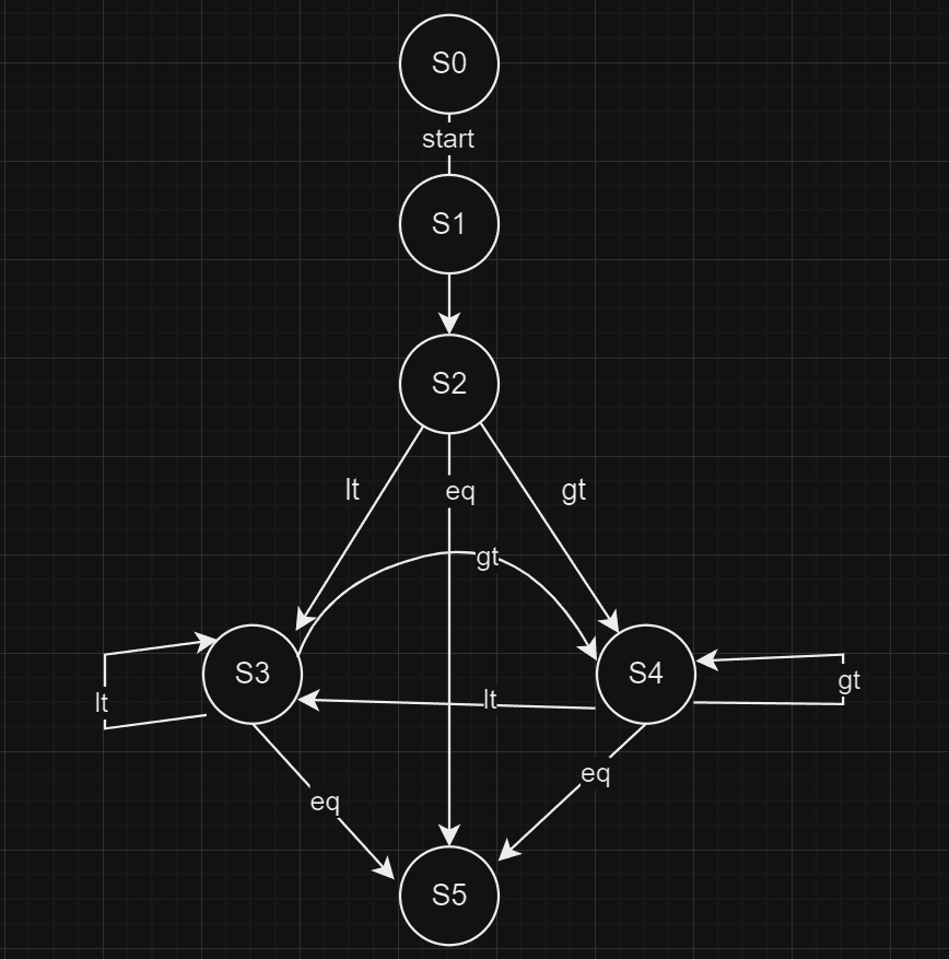
S0 (Initial State): Waits for the start signal.
S1 (load A and B): loads the input values into registers.
S2 (Comparison & Subtraction):
If A = B → Move to S5 (Done State)
If A > B → A = A - B
If A < B → B = B - A
S3, S4: Continue subtraction until A = B.
S5 (Final State): Outputs the GCD.
The control unit generates control signals (ldA, ldB, sel1, sel2, sel_in, done) to manage the datapath.
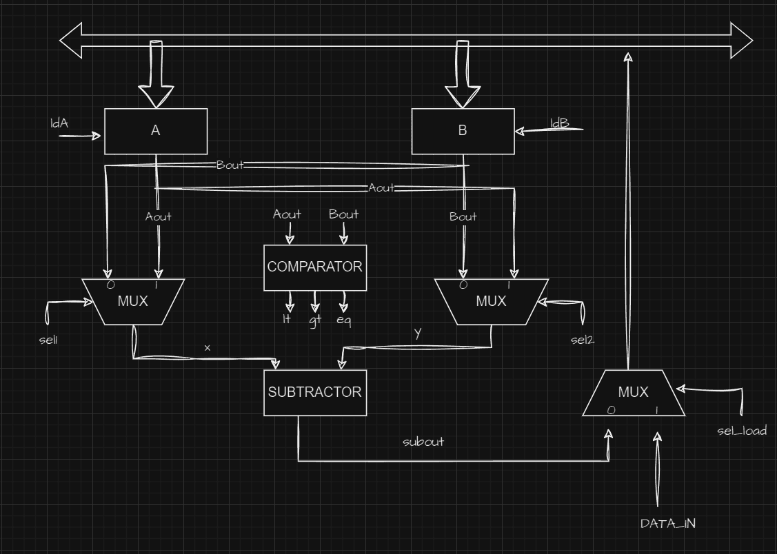
II. GCD Datapath
The datapath unit consists of:
Registers (
AandB) – Store the input values and intermediate results.Comparator: Determines whether
A > B,A < B, orA == B.Multiplexers (
MUX1,MUX2) – Select values for subtraction.Subtractor: computes the difference between the selected values.
Bus System: loads new values into registers based on control signals.
The datapath executes the arithmetic operations as per the control unit's signals.
III. GCD Testbench
The test bench is designed to:
Generate clock and start signals.
Load two input numbers (
A = 65,B = 13).Wait until the
donesignal is established.Display the final GCD result in the simulation output.
Conclusion:
This project efficiently computes the GCD of two numbers using Verilog HDL with a structured approach. The use of a separate FSM controller and datapath ensures modular design, making it easy to modify and extend for further optimizations.