Designing a 4×1 Multiplexer Using 2×1 Multiplexers in Verilog
Designing a 4×1 Multiplexer Using 2×1 Multiplexers in Verilog
Introduction
A multiplexer (MUX) is a fundamental combinational circuit that selects one out of multiple input signals and forwards it to the output based on the select lines. Multiplexers are widely used in data selection, signal routing, and digital logic design.
In this blog, we will design a 4×1 MUX using 2×1 MUX modules in Verilog, explaining the hierarchy and working principles.
What is a multiplexer?
A multiplexer (MUX) is a combinational circuit with:
Multiple inputs (data lines).
Select lines to choose which input gets forwarded to the output.
One output that carries the selected input value.
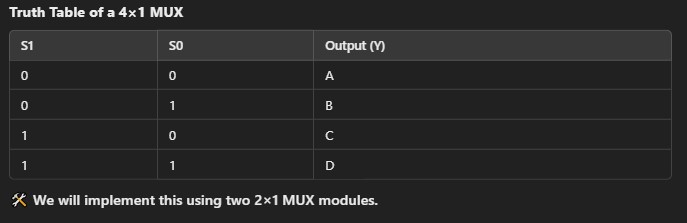
A 4×1 MUX has 4 inputs, 2 select lines, and 1 output. The select lines determine which of the four inputs appears at the output.
How to Implement a 4×1 MUX Using 2×1 MUX?
A 2×1 MUX selects one of two inputs based on a single select line (S).
The output equation is:
Y=(S⋅A)+(~S⋅B)Y
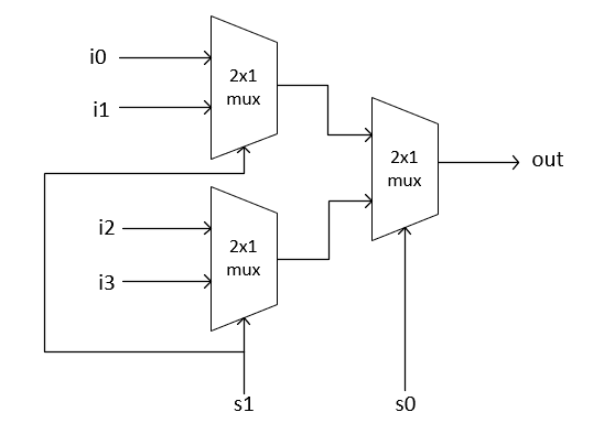
To design a 4×1 MUX, we use three 2×1 MUX modules in a hierarchical structure:
MUX 1: Selects between i0 and i1 (using S0).
MUX 2: Selects between i2 and i3 (using S0).
MUX 3: Takes the outputs of MUX 1 and MUX 2 and selects the final output using S1.
Verilog Code for 4×1 MUX Using 2×1 MUX
Step 1: 2×1 Multiplexer Module:
Step 2: 4×1 Multiplexer Using 2×1 MUX
Testbench for Verification
To verify our 4×1 MUX, we create a testbench that applies different input values and checks the output.
Simulation Output
After running the simulation, we expect the following output:
Conclusion
We successfully implemented a 4×1 multiplexer using 2×1 multiplexers.
The hierarchical approach allows modular design and reusability.
The testbench verified that the output changes correctly based on select lines.